A simple dehydrator build with temperature control
Step-by-step process (with pictures) of how I built a large capacity food dehydrator, including optional thermostat control of a heating element and ventilation. Includes all parts and detailed instructions.
Recently after many weeks of successful mushroom hunting, I quickly had more mushrooms than I knew what to do with, and I would hate to throw them out. Our apple tree also had a massive amount of fruit this year. One could save time and buy a dehydrator, but after looking online at the various options and trying to decide on what to do with some old roof sheathing (plywood) I decided to build one. This post details the build process step-by-step and includes useful tips and links (note, affiliate links support this website and future content). This is an intermediate project that anyone can do, it is well worth the effort!
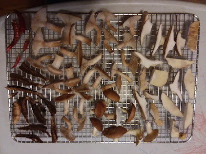 |
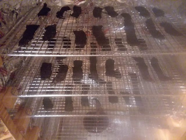
| A variety of wild picked mushrooms and garden peppers about to go into the dehydrator. |
This dehydrator has proven to be more useful and fun to use than I expected, we have used it to make home-made beef jerky (it can easily run over 180 deg. F!), apple chips, dried peaches, herbs, and others. After some research into similarly inspired projects I combined what I considered the best ideas into the design but kept it easy to make. It has a high capacity and can be used with different heating and ventilation units by simply plugging them into two outlets that are controlled by a built-in thermostat. I've also included some notes on modifying it to be more suitable for jerky with an internal fan. The total cost of this build for me was around $75. A list of materials used and links to purchase important parts and tools are provided. Hope you enjoy!
Legal Disclaimer: This project involved basic electrical wiring, even simple electrical work has inherent safety risks and can result in serious injury or death. If you do not feel comfortable making electrical connections ask for help from a licensed electrician. subcriticalflow.com cannot be held responsible for any injuries you may incur from building or using this dehydrator.
The box
- What are the dimensions (length and width) of your trays you wish to use in your dehydrator?
- What capacity or number of trays you do you need?
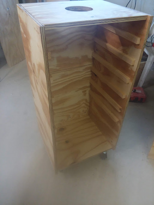 |
| The dehydrator is a simple plywood box, with a hole on top for the exhaust fan and a series of holes on the bottom of the walls for incoming air. |
Overall dimensions
Again, the width and depth were determined by the dimensions of the stainless steel cooling racks I use as drying racks which are 16.5 x 11.5", I kept the extra 4 1/2" depth to be able to keep the food a bit away from the walls to improve the drying efficiency, I also wanted to experiment with adding a horizontal fan inside and have enough room without interfering with the drying racks, but this is optional you could reduce the depth of your box to be more inline with the size of your racks.
A note on drying racks/material:
Cut list:
- 16" x 36" (2 pieces for side walls)
- 18 1/2" x 36" (back wall)
- 17 1/8" x 36" (door)
- 17 1/8" x 15 1/4" (2 pieces for top and bottom)
- 15 " x 3/4" x 5/8" (24 for for rack supports or your preference)
Assembly of the box
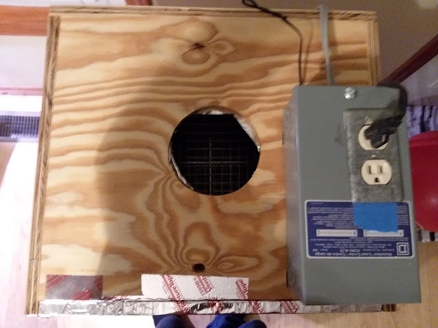 |
| View of dehydrator box from above, the front door is at the bottom of the picture and covered in aluminum foil for reference. |
Next, drill 1/2 or 3/4" inlet holes (about 2 inches from the bottom) in the side and back wall pieces every couple of inches angled slightly upwards from the outside in (picture below). You could also drill these holes in the bottom of the door but I didn't. Tip: put a piece of scrap material under your wall pieces to avoid tear out.
 |
| Side view of inlet holes near bottom of side walls and castors. |
I used a pocket hole jig and screws without glue to assemble the box and it is very strong and square. It would also be fine to drill pilot holes and screw, or nail (with glue) the box together but the angled pocket holes gives a lot more strength to plywood joints because they avoid screwing directly into end grain.
If you use pocket holes, layout your screw locations on all the pieces after you label them (back, side, top, bottom) and drill all the holes about 6-8 inches apart. Start by laying the back wall piece on a table or work surface and attach one of the side walls, a brad nail gun or corner clamp may be useful to hold the pieces aligned while you screw. The back and side walls are the same length and should be aligned lengthwise and connected at 90 degrees with the side wall should sit on top of the back (when the back piece is lying down). Next you can attach the top and bottom pieces which fit inside the back and side walls and are flush with their outer ends. Now you should have the back and one side wall connected lengthwise and along the top and bottom pieces, now the other side wall can be attached to the back and the top and bottom pieces from the inside. Look at the pictures above to see how the pieces should fit together once complete. Tip: set your drill to a low torque to avoid over driving screws and striping the plywood.
Now your box should look similar to the first picture without the wood strips installed.
Cut and install drying rack supports
Apply finish (optional)
Connect the door
 |
| Piano hinges used to attach door. |
Install a door latch
 |
| View of custom made door latch. |
Install wheels or bottom supports
You will need to put some sort of supports under the dehydrator, I used four 3" lockable castors which allow me to move the dehydrator easily but you could also use other supports. This is important because you will need some access under the box for the wiring to your heating element which will run outside and under the box up to the top where the thermostat is located.
Install electrical box and fixture for the heating element
Next, drill a 2" hole in the center of the bottom of your dehydrator using a hole saw or jig saw. This will be used to run wiring to an electrical box which will be used to hold the heating fixture (bulb fixture). The reason for the large diameter is to make it easy to connect a cable clamp to the electrical cable to the bottom of the electrical box so that it cannot be pulled loose accidentally, this is very important for safety!
You can use an old discarded extension cord for this like I did or buy a 14 gauge cord that is about 5 feet long and keep the male 3-pronged 120v plug attached. You will directly wire in the other end of the cable into the light fixture later. Install a 3/4" cable clamp into the bottom hole in a 4" electrical box and tighten it to the box leaving the cable clamp open. Next, attach the electrical box inside the dehydrator on the bottom using screws so that it is centered over the 2" hole. I recommend this 4" electrical box which is safe in damp conditions and a porcelain light bulb fixture to hold your heating element. Now run your cord through the bottom hole of your dehydrator and through the electrical box through the clamp with about 4 inches of the wires out of the cable sheathing using a cable stripper. Also strip about 1/2 to 3/4" of bare wire from the ground, neutral, and hot wires with a wire stripper and attach them to the bulb fixture, this is typically done by bending a partial loop (using the small hole in the wire stripper) in the three wires and pinning them down with the screws inside the fixture, making sure to connect the ground screw in the correct location of the fixture. Once the connections are made, pull any slacking cable through the bottom of the box and attach the fixture to the top of the electrical box with the supplied screws. Now finish up by tightening the cable clamp from below the dehydrator which should be accessible via the 2" hole that was drilled. Hold the male plug end of your cord and make sure that it can reach at least 8" above the dehydrator so it can be plugged into the box holding the thermostat.
The thermostat box and wiring (optional)
Before continuing, I think it is important to mention that installing this thermostat is optional. At this point you could plug a heating element, like a 250 watt infrared bulb into the bottom of your dehydrator and put the fan in the top and start dehydrating. From my experience this configuration will run at around 150-160 degrees F. with the fan on. You could experiment with different heating elements, a fan damper, etc to adjust your temperature and airflow manually. The neat thing about the thermostat setup is that it allows you to control the ventilation or heating element separately or in tandem, plus it tracks the temperature inside the dehydrator very accurately. For example you could plug your exhaust fan into the wall and the heating element into the thermostat so that the fan never stops running however the heating element will only kick on when the temperature falls below a certain level. When making beef jerky, I typically do the opposite using the thermostat, in other words I keep the heating element on and only turn the exhaust on if the temperature goes above say 175 degrees F.
Building the thermostat controller was a new thing for me and I found it enjoyable and will likely use this approach again if I ever need to control heating/cooling in other projects like a greenhouse.
The thermostat I used was the very affordable (about $16 dollars) Inkbird ITC-1000F which is commonly used by home brewers for their fermentation chambers. Hey, maybe after this project you can pick up a new hobby? I housed mine in a small electrical subpanel box simply because it was what I could find and was inexpensive. Although this works fine and is very sturdy, looking back I would recommend using a plastic "project box" because they are much easier to cut out the holes needed for inserting the thermostat and receptacle.
Steps:
Once you have your project box, take the tightening latches off the Inkbird and draw a rectangle in the front of the box that the Inkbird can fit into but the front will not fall all the way through. Also, draw a rectangle that is about a half inch smaller than the front cover for a regular 15 amp two plug receptacle on the top of your electrical box. Next cut these holes out with a Dremel/rotary tool and a cut-off wheel. Also knock-out or drill the appropriate size hole for a cable clamp for the power supply cord and drill a small ~3/8" hole in the back of the box for the temperature sensor to exit the box. The wiring diagram provided on the Inkbird will not work for this approach and is more useful for direct wiring.
Follow a good wiring diagram, here is the one I followed from the American Homebrewers Association:
 |
| Wiring diagram for connecting the Inkbird ITC 1000F (and other Inkbird 1000 series) to a receptacle for separate heating and cooling circuits. |
 |
| Side view of metal tab that needs to be removed from one side of the receptacle with needle-nose pliers. |
Once you have broken this tab, install your Inkbird into the front slot of your box, attach a cable clamp to the power supply hole you made and pull the power cable through it and into the box, separate a good amount of the individual cable wires (~ 6 inches) and strip the last 1/'2" or so. Also, from your spare cable, cut and strip 3 pieces of hot labeled wire that are about 6-8" and 4 neutrals, you can always shorten them later. Now follow the diagram to make the connections using appropriate sized wire nuts or locking connectors for the gauge wire you use in this box (typically 14 AWG). The connections to the thermostat itself are made by sliding the ends of the wires inside the terminals and pinning them down with screws that come with it.
 |
| A view of the thermostat box after making the wire connections from above. |
At this point it would be useful to mark which end of the outlet is connected to the cooling circuit and which plug is for the heating circuit on the outside of your box lid. Don't forget to also connect the provided temperature sensor to the thermostat and run the probe out through the box. I attached the whole assembly to the top of the dehydrator directly with screws. It can be tricky but I tightened the receptacle to the electrical box simply by tightening the screw on the from cover of the receptacle and positioning the receptacle so that it extends under the box lid, then by tightening the cover screw it pulls the receptacle body up against the box lid. Finally, tighten the cable clamp that holds the power supply cord into the thermostat box (image below).
 |
| View of thermostat box from the back and the cable clamp holding power supply. |
 |
| Front view of finished dehydrator with thermostat installed. |
Final touches
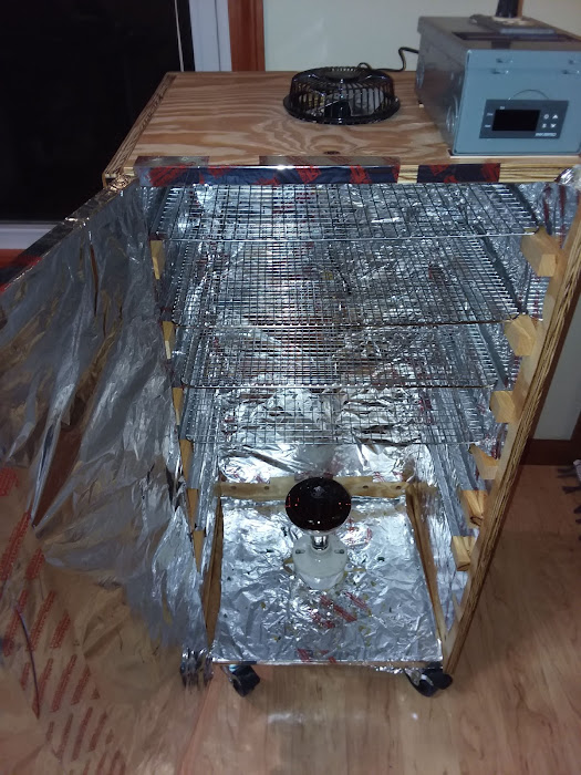 |
| View of the inside of my finished dehydrator, I used HVAC tape to hold down aluminum foil inside but a much better insulation system could be used. |
Congratulations!
Usage, experiments, and anecdotes
 |
| Beef jerky made using the dehydrator with horizontal airflow fan attached inside. |
The way I did this was I took a small ac motor (probably 5 volts or so) out of an old space heater someone threw away and mounted some cheap polycarbonate (heat resistant) R.C. airplane propellers to it, I couldn't use the fan blades provided because they were the wrong direction. You can see the red propeller blades in the back of the picture above if you squint.


I stumbled onto your blog while researching how to build a 3d printer filament dryer. I just thought I would let you know that your wiring explanation is...WRONG. You indicate cutting the metal tab on the LEFT side between the port #2 connection and the neutral wire coming directly from the power plug. However, it is, in fact, the RIGHT (Hot) that should be cut (Your "side view" picture is actually of the RIGHT side) It just drives me crazy when someone posts something online as if they are some type of expert and then gets it completely wrong! Especially when dealing with electricity that could potentially harm someone.
ReplyDeleteHey thinks for pointing out "WRONG" , he nver claimed to be so type of expert try not being so rude and live longer!
Deleteyes the typos are there to make you mad
DeleteThanks for posting, it has been corrected.
ReplyDeleteIts a good project
ReplyDeleteI realize one thing, I was using mild steel. But after seeing this I want to do wood. But I am using DHT 22 for control of heat and humidity. I am also using 7 bulbs for heat(100W) mahbe walls with two fans for circulation and exhaust of moisture. I am prototyping a fish Dehydrator.
ReplyDeleteThat's really cool, you should share an update. I'm interested in hearing how it goes.
DeleteI am also designing a fish dehydrator. I hope it will work well for your ideas. But do you need drainage
ReplyDeleteAnd can I also use normal wood instead of the plywood
ReplyDeleteAdditional ideas:
ReplyDelete* You can buy thermostat controls online. They have a sensor, a relay and you can set them to either open or close when above your set point. About 30 bucks.
* If you are willing to go bigger, look at starting with a either a fridge or a freezer. Premade box. You will have to make custom shelves. Consider either window screen or the coarse nylon mesh you can get at fabric stores.
* Alumunum slider windows are often avialable for free. A miter saw with a m etal blade, and you can make frames with these.
* The ideal would be to have a humidity sensor and a temkperataure sensor. Anb exhaust fan runs when the humdity gets above a certain amount. This is where sometihgn like an ardino or a raspberry pi would be handy. Humitity is going to to be high at first, and need lots of fentilation.
* If you want to save engery get a 100 foot section of black 6" drain tile, and lay it in the sun.
* Have one fan that just circulates air inside the cabinet. This will even out the tekmp fluctations. Otherwise you wil tend to get higher temkps at t he top.
* Having a set of remote digital thermometers in it will be handy for monito0ring temp and humidity.
Note that the seals on an upright fridge /freezer are not water tight. If you leave this outside, it needs a hat..
Note Initially with fresh food you may get away with jjust pumping air t horugh it as fast as you can.
* Inlet holes need to be screened so that even small flies can't get in. Fruit flies would love this. setup. And you don't want regular flies laying eggs in your jerky. Squirrels will also try to get in if you do this outside. In this case, you need both hardware cloth and fine mesh on ports.
All great comments, thank you! As an update this simple approach has worked great for drying things relatively quickly, I don't tend to use the thermostat much anymore, I tend to switch out bulbs for different temperatures depending on what I am drying and just leave the fan running. But for those looking to improve on this, these are good ideas.
DeleteWhat is the main heating element, bulb or thermostat ?
ReplyDeleteI used a 250 watt infrared heating bulb for high heat, sometimes smaller watt bulbs work for things like herbs.
DeleteThink you I need dehydrated on onions
ReplyDeletenice post
ReplyDelete